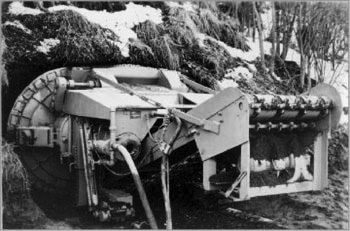
The Alkirk continuous-cycle mining machine (sketched above) was used to bore horizontally into the permafrost. The miner was moved up to the face where it was to begin excavation and pilot cutters would be extended into the soil about 2 meters. Packers would then be expanded around the pilot cutters lodging the pilot cutters in the soil. The cutters were then slowly retracted pulling the body of the machine into the face of the excavation, where the cutting disks would grind out the material. When the pilot cutters were fully retracted, they would be extended into the soil again to begin another cycle. Although it operated in cycles, the Alkirk created a smooth surface behind it. The cutter disks were over 2 meters in diameter, making it pleasant for miners to move about without hunching over. This ingenious device was used to excavate a continuous tunnel nearly around-the-clock, and was the pre-cursor to the modern tunnel boring machines used to excavate the Channel Tunnel connecting England and France.
During mining, an electric shuttle car was located behind the Alkirk and material was loaded into the shuttle car from the conveyor of the Alkirk. When the shuttle car was fully loaded, the excavation would stop and the shuttle car would pull out of the tunnel where it would unload itself into a spoil pile. The shuttle car would return to the excavation, and the spoil pile was relocated with a wheeled loader.

The Alkirk continuous-cycle miner machine beginning the portal excavation. |

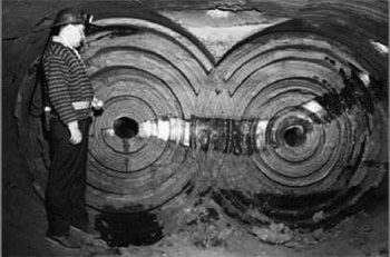
The double-circle excavation pattern created by the spinning disks of the Alkirk miner. |
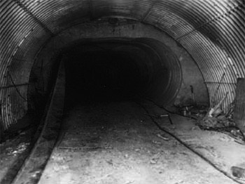
CRREL engineers ran two ten-hour shifts, finishing with a short maintenance shift. The first 2 meters of the excavation passed through what is known as the active layer, or seasonal thaw zone. In the thawed state this soil would not withstand its own weight without support. Because of this a semicircle of corrugated steel culvert was installed through the active layer and mechanical refrigeration coils placed in the soil to prevent the escarpment from sloughing over the entrance. The corrugated section was buried with soil and a layer of peat was added to help insulate the active layer and tunnel.
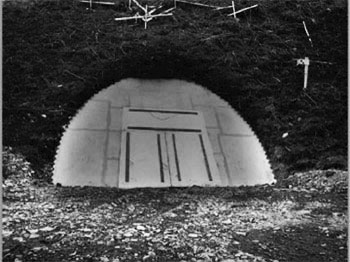
As the excavation progressed into solid permafrost, structural support was not required any longer as the frozen strength of the soil is sufficient to support the 15 meters of soil above. However, the active layer and portal insulation alone were insufficient to prevent the temperature from rising above freezing in the summer, so a refrigeration unit was added inside the tunnel to maintain below freezing temperatures. Construction was limited to winter months and in the summer the tunnel was sealed to avoid permafrost thaw and tunnel collapse.

The corrugated steel culvert protects the portal from sloughing soils. The permafrost can be seen just past the metal culvert. |

The tunnel was closed and sealed for the summer months during the years of construction. |